Open source is ready for prime-time! … sort of.
One of my favorite projects I’ve encountered in the last few years is ESPTimeCast. If you have a 3D printer and a little know-how, you can build an NTP-synced clock for ~$15-$20 and very minimal headache. It has an excellent, straightforward messaging API and integrates very cleanly with Home Assistant. It can show you weather, custom messages, you can configure the NTP server and brightness. And the whole thing can be built with off-the-shelf parts from Amazon and flashed directly from a chrome-y browser (including brave and basic chromium). I like them so much that I’m currently running three of them in my home and one in my office.
My other clocks utilize an ESP8266 board. Looking for a little more flexibility and horsepower (broadly, not just for the TimeCast) I decided to upgrade to an actual ESP32 Dev Board. There’s more pins and the pinout is different than the others. The TimeCast uses the “Serial Peripheral Interface” (SPI) to signal the LED matrix. Long story short, there are some mismatches between the default pinout listed on the github and the various documented pinouts.
Only two pins are switched, and I definitely tried the quick fix of switching them, but for some reason my initial attempts did not work. I was actually unable to even flash the first board. The second board flashed just fine, however seemed to have the same confusing pin swap which I could not resolve by just swapping the attachments.
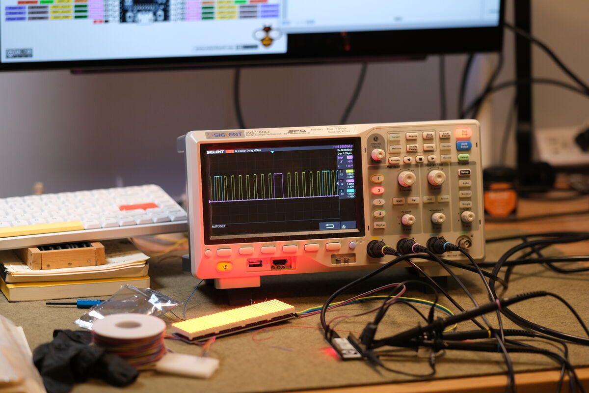
This is all building to me sharing the above picture of debugging the raw signals directly using my oscilloscope, confirming that the Github pin listing is correct. The purple trace (attached to GPIO pin 23) is the “CS” (or chip select) signal. When it goes low (Transitioning from 3.3V to 0V), the clock (yellow, GPIO pin 5) and data (blue, GPIO pin 18) lines start handling the data sequencing. Pretty cool, right? We can just directly measure the output to determine which pins are sending what. I love this stuff. Look at all the wires and blinky lights!
It did give me pause though: this is exactly the kind of ambiguity or frustration that will set back an enthusiastic but unskilled novice. Heck, it set me back on my first attempts, which I haven’t come back to until today and took well over an hour to debug. Furthermore, I doubt many have an oscilloscope on hand to do this sort of validation, although they are getting cheaper and more widely available.
The first three clocks were easy though, so credit where credit’s due: this is still a great concept and exactly the type of special purpose computing I hope to see more of in the future, as general purpose computing is turning into a general purpose nightmare a little bit more every day.
Open source’s reckoning
I think the beauty of the free/open/libre software community is that they can pick whatever the heck they want to do with their code, as well as the intended audience. I love recommending things to people, but I’m also starting to realize how far off of the “norm” I am in estimating complexity and difficulty. Not every project needs to be for beginners, but let’s also make sure we try to inspire people to get into this stuff. I’d put ESPTimeCast at a solid low-intermediate with excellent documentation.
We enthusiasts that can help translate may bear some responsibility to help teach and communicate methods and learning as much as possible in the new era of computing landing on top of us. The non-free computing is more accessible to non-experts, but it’s also corrupt, loaded with advertising and literal gambling and porn, and awful and manipulative to work with (I have to use windows at work for a few tasks… yuck). It’s literally built to be as addictive or “engaging” as possible. Think about that. Does that respect your time? Does a casino value you for more than your wallet?
Final thought: wire-wrapping is amazing
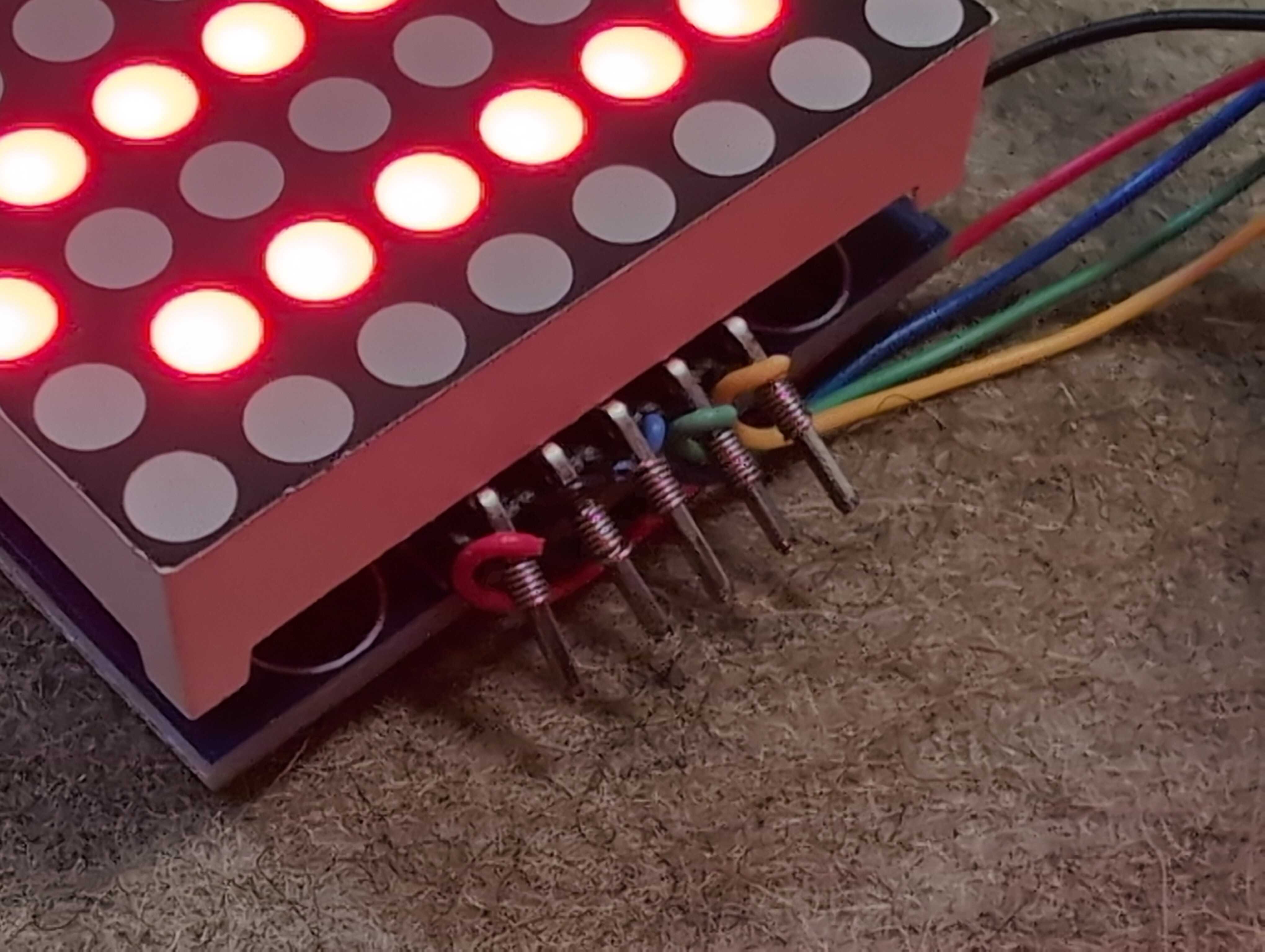
I’ve increasingly been sick of soldering. I recently picked up a wire wrap tool and some wire and *chef’s kiss* what a more pleasant, clean, and less toxic approach to bonding/attaching wire. No burns. No smoke. No accidentally cooked chips. It’s not suitable for all applications, but works here. Another tool in the toolbox from yesteryear of computer building. If you want to see an incredible home-built CPU using wire-wrapping, check out Bill Buzbee’s homebrew CPU the Magic-1.
Finding and reading about his project during a pivotal moment led me to build my own (I’ll write more soon) and literally changed my life. Thanks, Bill. :)
2026-10-24 Here:Now:Present